For a Complete Assembly, Please Select:
SWITCH
 |
Switch Amp Rating | No. of Poles | SCCR @600V | Max Class J fuse | Max Horsepower Rating,3-Ph | Wire Size | Wire Type | Part Number | |||
| 208Vac | 200/240Vac | 440/480Vac | 600Vac | ||||||||
| 16 | 3 | 65kA | 30A | 3 | 5 | 10 | 10 | #14-#10 Sol Dual #12 Sol #14-#4 Str dual #14-#12 Str | 75°C Cu | RD16-3-508 | |
| 25 | 3 | 65kA | 30A | 7.5 | 7.5 | 15 | 20 | #14-#10 Sol Dual #12 Sol #14-#4 Str dual #14-#12 Str | 75°C Cu | RD25-3-508 | |
| 40 | 3 |
10kA 65kA |
60A 30A |
7.5 | 7.5 | 20 | 25 | #14-#10 Sol Dual #12 Sol #14-#4 Str dual #14-#12 Str | 75°C Cu | RD40-3-508 | |
| 63 | 3 |
50kA 65kA |
100A 60A |
15 | 20 | 40 | 40 | #14-#10 Sol Dual #12 Sol #14-#1 Str dual #10-#6 Str | 75°C Cu | RD63-3-508 | |
| 80 | 3 |
50kA 65kA |
100A 60A |
15 | 20 | 40 | 40 | #14-#10 Sol Dual #12 Sol #14-#1 Str dual #10-#6 Str | 75°C Cu | RD80-3-508 | |
HANDLE
 |
Direct Mount Handle - mounts directly to switch, no shaft required | ||||
| For Switch Part Number | Color | Test Function | Padlockable | Part Number | |
| All Switches | Black | N | Y - On Switch | DIR-01 | |
 (1) (1) (2) (2)+  +  +  |
External Front or Right Side Operated Selector Handles - shaft required | ||||||
| NEMA Type | Color | Handle Length | Test Function | Padlockable | Defeatable | Part Number | |
| 1, 3R, 4, 4X, 12 | Black | Short | N | Y | Y | H4X-01B(1) | |
| 1, 3R, 4, 4X, 12 | Red/Yellow | Short | N | Y | Y | H4X-01R(1) | |
| 1, 3R, 4, 4X, 12 | Black | Long | N | Y | Y | H4X-02B(2) | |
| 1, 3R, 4, 4X, 12 | Red/Yellow | Long | N | Y | Y | H4X-02R(2) | |
| Shafts for Selector Handles - required for 12.6” (320mm) shafts | |||||||
| Length - in(mm) | Mounting Depth (X) in (mm) | Part Number | |||||
| 5.9 (150) | 3.50-7.60 (89-193) |
 |
SH4-150 | ||||
| 7.9 (200) | 3.50-9.50 (89-241) | SH4-200 | |||||
| 12.6 (320) | 3.50-14.9 (89-378) | SH4-320 | |||||
| Shaft Guide | |||||||
| Part Number | |||||||
| Required for 12.6” (320mm) long shafts, optional for other lengths. | SH-GUIDE1 | ||||||
|
Door Mount Kit - for mounting switch on the right side of the enclosure or directly on the enclosure door using switch side operation shaft location. Kit includes a shaft. Order switch and selector handle separately. |
|||||||
| Switch Rating | Part Number | ||||||
| All Switches - kit includes shaft | DOOR-508 | ||||||
AUX CONTACTS
 |
Auxillary Contacts | ||||||
| Contact Type | Number of Contacts | Continuous Amp Rating | Voltage Rating | Max Number of Aux Contacts per Switch | part Number | ||
| NO + NC | 1 Ea | 10A | 240Vac | 4 | BAC01 | ||
| NO | 2 | 10A | 240Vac | 4 | BAC02 | ||
 Auxiliary Contact Configurations
SHROUDS
 |
Terminal Shrouds - includes terminal shroud for both lineside and loadside | ||||||
| Switch Amp Rating | Number of Poles | Location of Switch | Part Number | ||||
| 16-40A | 1 (for switched 4th pole) | Lineside and Loadside | TSH1-1TB | ||||
| 16-40A | 3 | Lineside and Loadside | TSH1-3TB | ||||
| 63-80A | 3 | Lineside and Loadside | TSH2-3TB | ||||
SW. 4TH POLE
 |
Switched 4th Pole - converts 3-pole switch to 4-pole switch | ||||||
| Switch Amp Rating | Part Number | ||||||
| 16 | POLE-16 | ||||||
| 25 | POLE-25 | ||||||
| 40 | POLE-40 | ||||||
6-POLE KIT
 Order switches separately. |
6-Pole Conversion Kit - creates a 6-pole switch by ganging two 3-pole switches of equal rating | ||||||
| Switch Amp Rating | Part Number | ||||||
| All Switches | KIT-6POLE* | ||||||
|
* Kit ships with a direct handle. If external handle is needed order a selector handle and shaft for the UL 508 Rotary Disconnect Switches. Note: To create an 8-pole switch from 16 to 40 amp switches, use two 3-pole switches of equal ratings plus two switched 4th poles (part # POLE-_). |
|||||||
 Switched 4th Pole Configurations.
Dimensions – in (mm)
Direct Handle Operation

External Front Operation

External Side Operation

Direct Front Operation for 6/8-Pole Disconnects

1. Position for 1 switched 4th pole (1 per device max.) or 1 auxiliary contact.
2. Position for 1 auxiliary contact only.
Note: Maximum of 4 auxiliary contacts, or 3 auxiliary contacts + one switched 4th pole.
External Front Operation
External Side Operation
|
Switch Rating (A) |
Overall Dimensions |
Terminal Shroud AC |
Switch Body |
Switch Mounting |
Connection T |
|||||||
| D min | D max | E min | E max | F | F1 | G | J | M | N | |||
| 16 to 40 |
1.18 (30) |
9.25 (235) |
3.94 (100) |
14.64 (372) |
4.33 (110) |
1.77 (45) |
0.59 (15) |
2.67 (68) |
0.59 (15) |
1.18 (30) |
2.95 (75) |
0.59 (15) |
| 63 to 80 | 1.18 (30) | 9.25 (235) | 3.93 (100) | 14.64 (372) | 4.33 (110) | 2.06 (52.5) | 0.69 (17.5) | 2.99 (76) | 0.69 (17.5) | 1.38 (35) | 3.35 (85) | 0.69 (17.5) |
Direct Front Operation for 6/8-Pole Disconnects
1. Position for 1 switched 4th pole (1 per device max.) or 1 auxiliary contact.
2. Position for 1 auxiliary contact only.
Note: Maximum of 4 auxiliary contacts, or 3 auxiliary contacts + one switched 4th pole.
External Front Operation for 6/8-Pole Disconnects

External Selector Handles
Handle Type

Direction of Front Operation
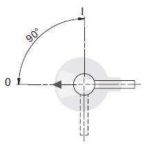
Direction of Right Side Operation

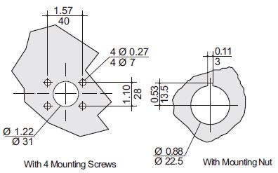
Door Drilling Layouts
External Front Operation for 6/8-Pole Disconnects
|
Switch Rating (A) |
Overall Dimensions |
Switch Body |
Switch Mounting |
Connection | |||||||
| E min | E max | F | F1 | F2 | G | J | M | N | T | X | |
| 16 to 40 | 4.13 (105) | 14.64 (372) | 3.83 (97.5) | 0.59 (15) | 1.77 (45) | 2.67 (68) | 1.92 (48.75) | 1.18 (30) | 2.95 (75) | 0.59 (15) | 0.29 (7.5) |
| 63 to 80 | 4.13 (105) | 14.65 (372) | 4.13 (105) | 0.69 (17.5) | 2.06 (52.5) | 2.99 (76) | 2.06 (52.5) | 1.38 (3.5) | 3.35 (85) | 0.69 (17.5) | 0.34 (8.75) |
External Selector Handles
Handle Type
Direction of Front Operation
Direction of Right Side Operation
Door Drilling Layouts
总机: 0755-82862885, 82862629
传真: 总机 转 801
邮箱: service@bussmann.net.cn
网址: http://www.bussmann.net.cn
资料中心: http://www.bm-bussmann.com